
Race Engineer
Race Engineer: Car Creation System
Matt Ager
Car Creation System In Race Engineer
Why:
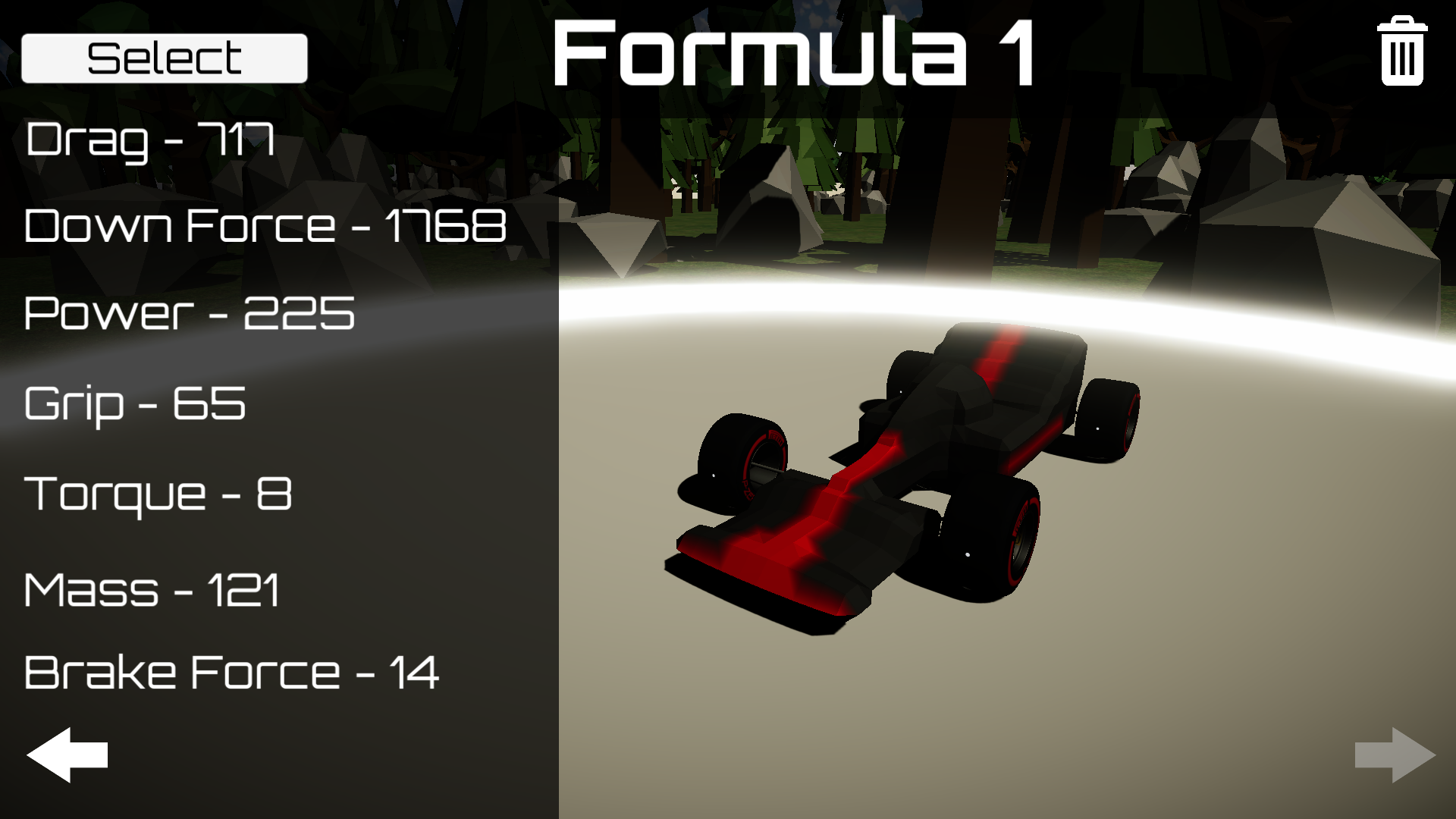
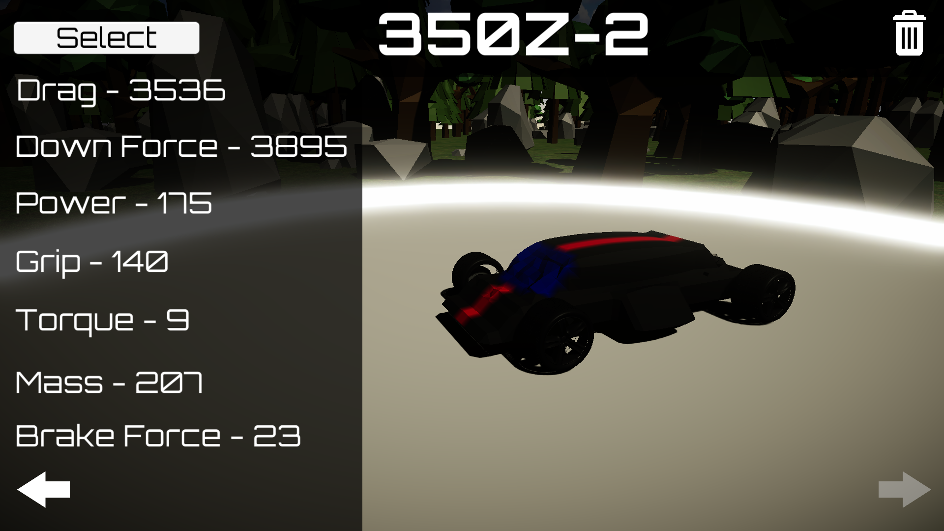
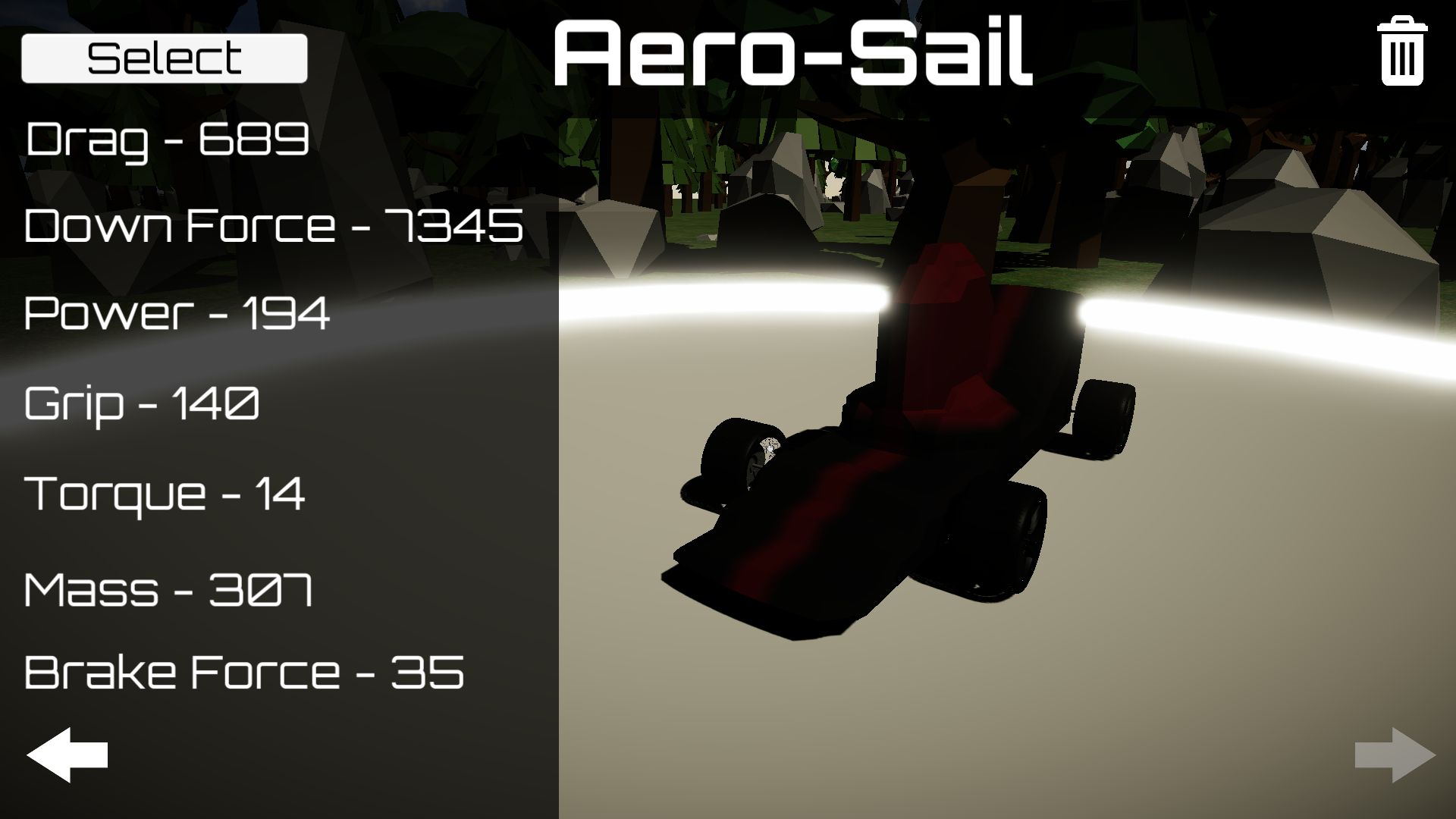
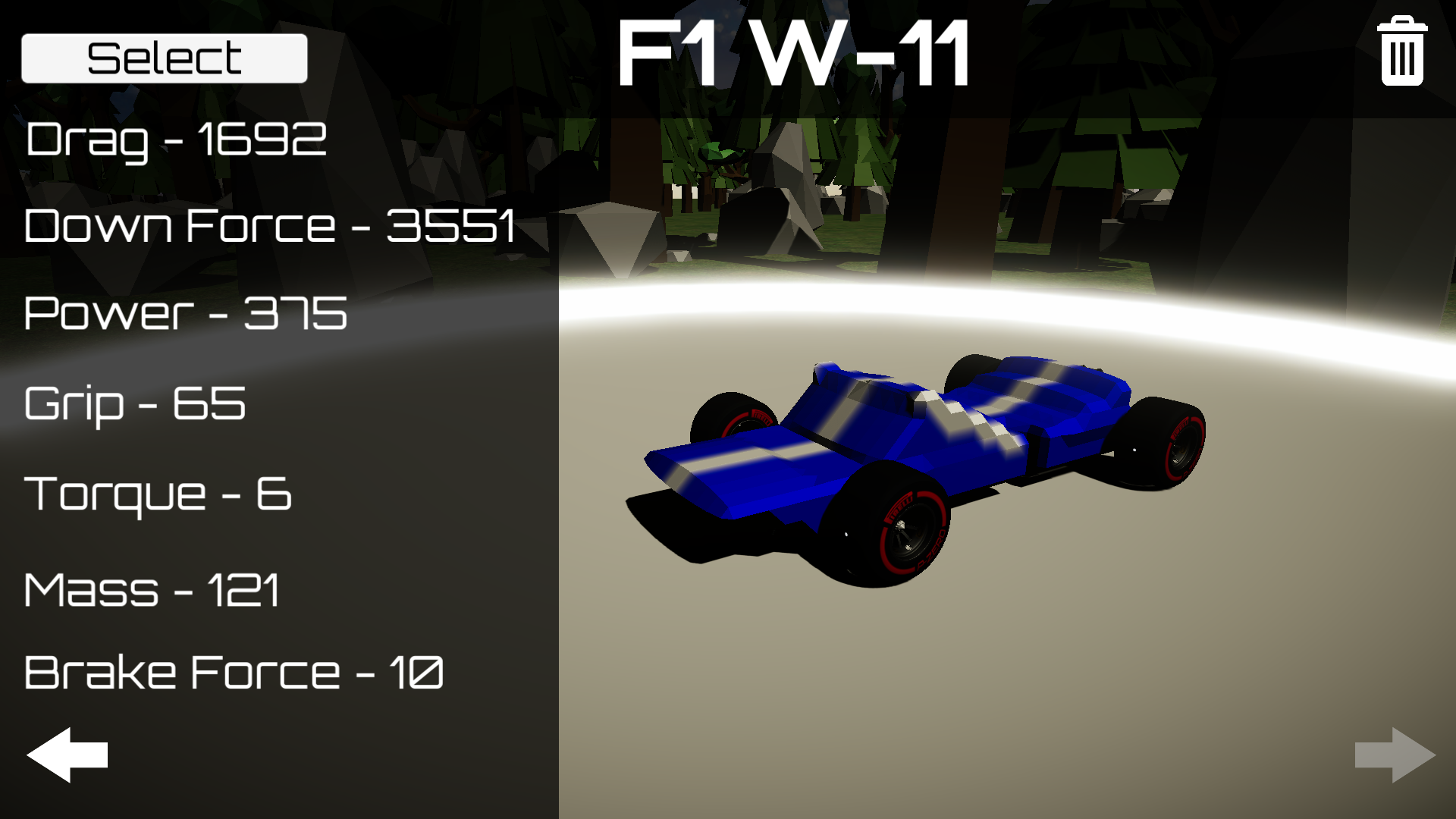
The goal of the car creation system in Race Engineer was to provide the player with another option to overcome challenges in the game besides simply racing faster. It enables the player to create a car to fit the specific characteristics of the track. If a track has long straights and easy braking zones, the player may want to create a car with less downforce and a more powerful engine. If the track has tight turns and hard braking, the player may want to create a car with good handling and sacrifice some speed. Of course, the player can try to complete each track with the same car, however each track is designed with a unique driving style in mind.
What:
The creation system is organized into three sections: wheels, engine, and body. The wheels have an effect on the mass of the car and the grip on the track. Lighter wheels have less grip, and vice versa. The engine has an effect on the power, torque, and braking power of the car. An engine with a higher power, will have less torque (analogous to acceleration at low speeds), and lower braking power. Finally the body has an effect on the mass and aerodynamic characteristics of the car. A body with better aerodynamics will probably be heavier than a more simple car without as much modification, however the player has a lot of freedom to maximize the effectiveness of the car.
How:
(The systems governing the wheels and engine placement and modification are very straight forward and will not be discussed in this article.)
The body of the car is represented by a mesh which can be edited freely by the player. The mesh generation algorithm used to create the car is Marching Cubes. For more information on the Marching Cubes algorithm, read this article about the 2D analog to marching cubes https://catlikecoding.com/unity/tutorials/marching-squares-series/. I chose this algorithm because it allows the player to use the most intuitive set of simple tools to craft the car. The tools the player can use to craft the car are simply meshes which only add or subtract from the value of the points in the Marching Cubes node array which are intersecting the tool mesh. Therefore the first problem we must solve is being able to tell if a point is inside of any mesh shape. Some simple shapes have intersecting functions which can run quickly and efficiently, such as spheres and cubes. It is very simple to tell if a point is within a sphere as all you have to do is compare the distance from the center of the sphere to the point and the radius of the sphere. However it is much more difficult to find if a point is within a custom shape with no known intersection function. To find if a point is within this type of shape we can use a technique involving Unity’s raycast function. First, we move the collider which represents the tool to its own layer and mask the raycast so it only intersects with the collider we care about. Next we cast a ray from any point which we can assume is outside the collider (ie (-1000, -1000, -1000)), to the node we are calculating. Each time the ray detects an intersection we increment a counting variable. After each intersection we can check to see if we have passed the node. If the dot product of the direction of the ray and the direction from the ray to the node is -1, we have passed the node. After we reach the point we send a raycast back to the origin of the ray and count any faces of the tool in the other direction to account for backface culling. An alternative option to account for backface culling is to simply turn backface culling off in Unity’s physics setting before raycasting and then turning it back on after we calculate the intersection. Finally after counting the total intersection with the tool’s collider we can discover the intersection state of the point. If the intersection count is even or 0, the point does not lay within the shape, but if the interaction count is odd the point does lay within the shape. An easy way to intuitively understand why is to imagine a sphere is space and a point traveling towards the sphere. Image the point passing through the sphere and count the points intersections with the sphere. When the intersection count of the point is 0, the point obviously is outside the sphere. As the point intersects the sphere for the first time it is inside of the sphere. And finally as it exits the sphere we count another intersection. The point is only within the sphere at an intersection count of 1. Now imagine more complex shapes and the intersection of a point as it travels through them and you will quickly understand this technique. Now that we can use any mesh as a tool, we can focus on what tools the player would want to have at their disposal. Simple tools like a box, sphere, and capsule are mandatory for creating most designs. Objects such as cones, spirals, and wedges are also very useful. The tool shapes alone are not enough to build each design. The shapes also need an effect gradient function.
The Gradient Function:
The gradient is the most important addition to the tool suite found in Race Engineer. This is due to the mesh generation strategy. (The following assumes a basic understanding of marching cubes using interpolation). If we use the capsule tool we want to create a long capsule shape along a flat part of the chassis to reflect air flow off the car and reduce drag. This is not easily possible without the use of the gradient. Since a point will either be inside or outside of the capsule each point within the capsule will be affected with the same increase in value. This will result in much less of a capsule shape, rather it will appear very boxy and geometric. However if a gradient in the effect of the capsule existed, the difference in the increase in value of each node will result in a smoother capsule-like appearance due to the interpolation of the nodes caused by the Marching Cubes algorithm. We give the player choice in how the gradient works. They can decide if the gradient is on or off, and how the distance is calculated from the tool to the point. The distance can be calculated from the center point of the mesh, or from any axis of the object. Without the gradient function, cars would begin to look “samey” due to their defined, boxy, voxel-like, appearance.
Painting:
The final step of the car creation process is painting the mesh. To do this Race Engineer uses a vertex shader (made in Unity’s shader graph), to color the mesh based on vertex color. Each Mesh class has a “colors” variable which is an array of Color (essentially a Vector4(r, g, b, a)). Each color’s index is the same as the index of the vertex it represents in the vertices array of the Mesh. To paint the car, the player simply clicks the car, and vertices within a certain distance from the point they click are colored. This color array is stored as a multidimensional float[meshVertices.length][4] for serialization reasons as the BinaryFormatter in C# cannot serialize unity’s Color class.
Conclusion:
The car creation system in Race Engineer streamlines a complex process so that it feels intuitive for the user. The system allows for freedom with its extensive and customizable tool set without overwhelming the user with hundreds of option which have little to no use cases. The trade off between intuition and complexity is a difficult line to balance on, but erring on the side of intuitive is a better option. The last thing you want as a developer is to either lose your players interest will a complex tutorial or having the player feel overwhelmed and give up on the game. For a game, especially a free one, to compete, it is mandatory that it does not introduce complexity quickly without a compensating tutorial. Since Race Engineer falls into this category of short playtime, free games, it must not fail to communicate how its systems operate.
Get Race Engineer
Race Engineer
Build, Refine, Race!
| Status | Released |
| Author | Matthew Ager |
| Genre | Racing, Action, Adventure, Simulation |
| Tags | 3D, Arcade, Experimental, Exploration, Low-poly, Singleplayer, Unity |
| Languages | English |
More posts
- Race Engineer: Post MortemDec 15, 2020
Leave a comment
Log in with itch.io to leave a comment.